Technics SL-P3 CD Player
 The first CD player from the Japanese brand to boast real 'kerb appeal', this mid-'80s machine also inherited key technology from previous models. How does it sound today?
Any early Compact Disc player from Matsushita (Panasonic/Technics) holds a particular fascination. The company was excluded from the top table when the CD format was created, in spite of (or perhaps due to) its pre-eminent position as the world's largest producer of electronic consumer goods.
As a result, the first Matsushita CD player, which was marketed in the UK as the Technics SL-P10 [HFN Oct '12], had to be reverse-engineered from the famous Philips/Sony 'Red Book' standard. Furthermore, every component within the player, from the most complex IC to the most mundane resistor and capacitor, came from within the Matsushita organisation – a true tour de force.
Small Wonder
Impressive though its gestation was, the SL-P10 was really a costly factory prototype that had been accelerated into production. The follow-up SL-P50 was little better, being aimed largely at the professional user and therefore far too large, too expensive and too short on style to suit the designer interiors of trendy early '80s buyers.
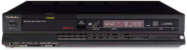
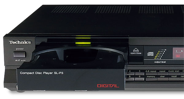
The next offering was the SL-P7, which arguably went too far the other way. Midi-sized and with controls akin to those of a child's first cassette recorder, it was perhaps too basic to reflect CD's high-tech image. It therefore took until 1985 for Technics to have something in its UK catalogue with genuine appeal. The new players came in a three-model lineup: the SL-P1, SL-P2 and SL-P3. All were basically the same machine but with extra features added as the range ascended. The SL-P3 we have here was the top model, second only to the SL-P50 in price. At around £480 it cost as much as two Philips CD 150s, plus a couple of discs to play on them.
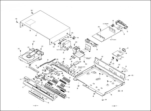
The two most intriguing things about the SL-P3 were both inherited from previous models. The first was the condensing of all the digital signal processing functions onto a small ceramic module, first seen in some versions of the SL-P50. In previous models these components would have occupied a substantial printed circuit on their own, but the use of large scale integration (LSI) techniques and high-density surface mounted IC packages reduced the whole assemblage down to something scarcely larger than a matchbox.
Military Spec
The player's decoding and error-correction all unfolded within this unit. It took in the off-disc data stream from the laser pick-up and delivered 16-bit parallel data to the DAC. In total, five IC packages were used in the module, all of Matsushita origin. This extreme miniaturisation was not strictly necessary because, like standard-sized CD players of the future, the SL-P3 contained a lot of empty space. The materials and assembly methods used were more similar to those found in industrial and military electronics than in the consumer sector and promised high levels of reliability. To this end, the modules employed in the SL-P3 were further sealed in a coat of clear resin to prevent any ingress of moisture.
Shift Work
The other noteworthy feature of the SL-P3 was its phase-shifting network. Suggested by the UK importer, this could be found only in the left channel of the machine's analogue sections and had previously been seen in the SL-P7. It is usual practice when designing stereo equipment to ensure that the left and right channels are as identical as possible in order to secure the same characteristics in both. Anything diverging from this rule is rare.
The only other example that comes to mind is the B&O Beolab 5000 amplifier [HFN Dec '13], which has an inverter in its left channel in order to make optimal use of the output of its power supply. The reason behind the Technics circuit has been mentioned in these pages before and it stems from the drawbacks of the use of a single DAC and no oversampling – as with almost every early Japanese CD player.
The stereo signal comes off the disc one sample at a time, alternating between the left and right channels. European players based on the Philips system store this data so that left and right sample pairs are available simultaneously to two DAC circuits. Yet it was the preferred method of Japanese designers to use a single DAC, time-shared between the two channels. Even those players that had two physical DAC chips (Yamaha's CD-1 and the Sony CDP-701ES, for example) still alternated the signal in this way.
This matters little at low and midrange frequencies, but at the upper limit of the CD system's range (22kHz) it results in a phase lag of 90o, essentially half way to having one of your loudspeakers wired up in reverse. The result is often heard as chaotic and smeared imaging, although the practice remained common in Japanese players until the 1986/1987 season.
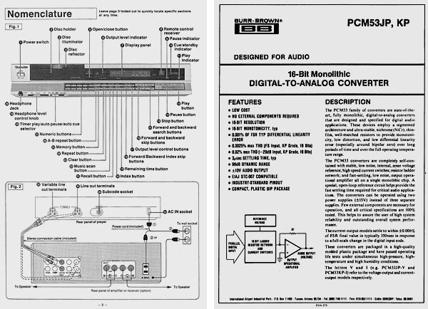
The SL-P3 has a single, time-shared DAC, although it is interesting that a Burr-Brown PCM53 type was used in preference to the in-house Matsushita device found in the SL-P7. The phase-shifting circuit can be found in any textbook of operational amplifier design.
Acoustic Alchemy
Here, the designer merely has to specify the required phase shift and the frequency at which it is to occur, the values for a single resistor and capacitor pair being the outcome of the equations. At first this almost seems like alchemy – can the answer to what appeared at first to be an intractable problem really be this simple? Circuit analysis proved that the Technics arrangement does indeed generate a
near-perfect 90° phase lag in the left channel at 22kHz, with no apparent effect on the stage's frequency response. Playing the frequency sweep on my test CD [Philips 426 689-2] via our SL-P3 into a dual-beam oscilloscope confirmed that both channels remained in phase throughout. By comparison, the same test conducted with a Sony CDP-101 showed the right channel predictably slipping behind the left as the frequency increased, reaching the expected 90° of lag at the top end.
This is all well and good, but as any audio designer knows, there is a world of difference between precisely generated test tones and the ever changing and complex mixture of frequencies and levels found in recorded music. For instance, how would such a simple arrangement work when a number of different frequencies are present at the same time, or when a particular tone is only present very briefly?
Slide Show
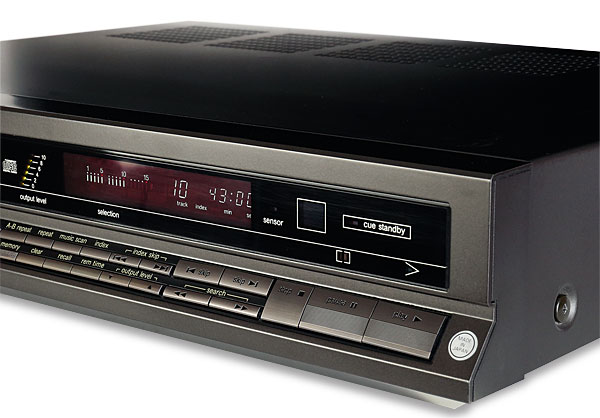
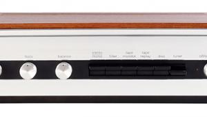
Putting the technical details aside, the SL-P3 is a singularly attractive machine. It is slim, wide and immaculately constructed – I'd even go so far as to say that 1980s Technics build quality was unbeatable compared with its rivals at the time. Yes, there are many controls, but they are perfectly scaled. Nothing is so large as to be toy-like, or so small as to be unusable. I especially liked the separate 'skip' and 'search' keys and the numerical keypad that enables direct track access.
|
| |||||||||


| Equipment Reviews | Music Reviews Awards | Latest News Features | Resources Newsletters | Subscriptions |
WHERE TECHNOLOGY BECOMES ENTERTAINMENT
 © 2026 Hi-Fi News
AVTech Media Ltd
All rights reserved