To the ends of the earth
Shortly after my first Investigation into headphone headband resonance was published [see HFN Jun '14], Owen Jones – he who designed THX's Achromatic Audio Amplifier circuit – pointed out to me that I could have done a better job of it.
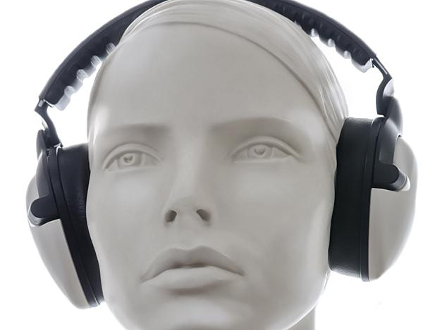
I'd deployed the artificial head I use for headphone measurement in a seemingly odd way: to measure the output not of the headphone's active capsule but its inactive one.
By comparing the frequency response obtained in this way to the one obtained from the active capsule, it was possible to see – in the case of headphones with headband resonance issues – obvious peaks in the inactive capsule response which were caused by the headphone structure going 'boing' at certain frequencies.
Rarely Mentioned
Exactly how significant such resonances are when using headphones normally to play music has not, so far as I know, ever been established. In fact headband resonance has been an elephant in the room for headphone design.
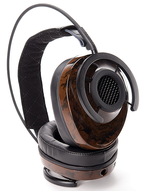
Manufacturers often talk about using low-resonance materials in their headphones' capsules, but the headband is rarely mentioned in this context: it merely exists to link the two capsules together, and is conveniently assumed to be vibrationally inert. But often it isn't, and only with a headphone like the AudioQuest NightHawk [HFN Sep '15] – which compliantly isolates the capsules from the headband – is it reasonable to make that assumption.
My measurement method probed the issue of headband resonance and showed it to be quantifiable in an acoustically relevant way (ie, not by sticking an accelerometer somewhere on the headband and then speculating about the acoustic effect of the resonances thus revealed...). It was neat, it was simple, it gave interesting and pertinent results.
But what I hadn't done, Owen pointed out, was eliminate electrical crosstalk between the two capsules caused by the common earth wiring often employed in unbalanced headphones. Here the ground terminals of the left-channel and right-channel capsules are linked within the headphone, so that a three-wire connecting lead can be used instead of a four-wire one: left signal, right signal and common earth. The common earth impedance means that signal current flowing through one capsule results in a crosstalk voltage appearing across the other capsule – and vice-versa.
Because the left and right signal earths are connected within the headphone, they cannot be separated without invasive surgery – not something that can be undertaken with review samples.
But you can easily open-circuit the signal connection to the inactive capsule, to leave the circuit depicted diagrammatically in Figure 1.
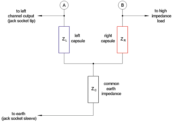
Not only does removal of the signal connection prevent electrical crosstalk current from flowing through the inactive capsule, it also allows the electrical crosstalk to be measured by comparing voltages at points A and B in the circuit.
The Adapter
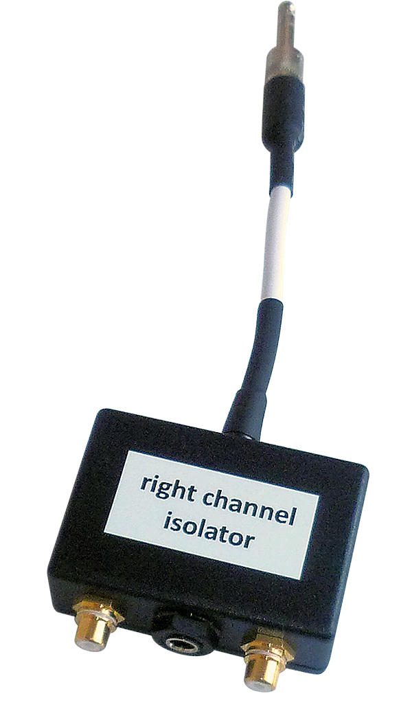
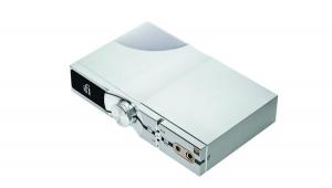
Not a finger need be laid on the headphone to achieve this: it can be implemented using an adapter inserted between the output of the (stereo) headphone amplifier and the headphone itself.
A picture of the one I built can be seen below: the jack plug connects to the headphone amplifier, the headphone under test plugs into the adapter's jack socket, and the two phono sockets connect to points A and B in the circuit. In my adapter the left headphone capsule is connected normally and the right capsule isolated, but it could as well be the other way round.
The Results
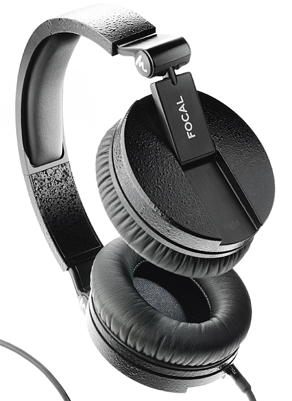
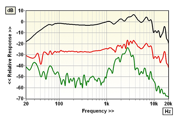
What results do we get using the adapter to remove electrical crosstalk in headphones with common earth impedance? Figure 2 shows an example, the headphone in this case being the Focal Spirit Professional that I reviewed recently [see HFN Dec '15].
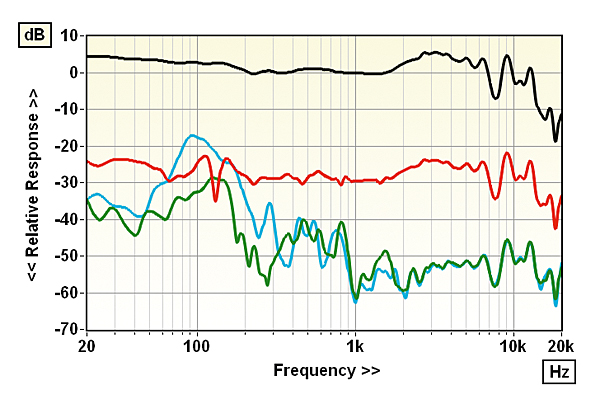
Subjectively this headphone has an obvious headband resonance issue, by which I mean that in the impedance test I conduct for the lab report – which involves the headphone being worn while a pink-spectrum periodic noise test signal is played over the left capsule only – coloration of the noise and migration of the sound from the left towards the inactive right capsule could clearly be heard.
Both are indicators that the headband is not the acoustically inert structure we would hope it to be. Three of the four superimposed traces in Figure 2 show: 1) the uncorrected frequency response of the left capsule of the Focal Spirit Pro review sample (black trace); 2) the response measured at the right capsule – as before, on the artificial ear – when the left capsule is driven without the right capsule being open-circuit (red trace); and 3) the response measured at the right capsule when the left capsule is driven but now with the right capsule open-circuit to prevent electrical crosstalk from the common earth wiring (green trace).
All three of these responses were measured with the headband resting on the artificial head; the fourth trace (blue) shows the effect, with the isolator in circuit, of lifting the headband out of contact.
It's clear from the blue trace in particular that the Spirit Pro has a headband resonance issue, and that the use of the isolator makes this much clearer.
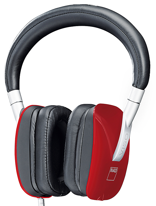
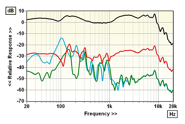
Two headphones measured in the earlier article were the NAD Viso HP50 [see HFN Jan '14] – which subjectively has a severe headband resonance issue – and the now discontinued Sony MDR-MA900 [HFN Oct '12], which subjectively (in the impedance test) seems to be resonance-free.
igures 3 and 4 show the results of retesting these models with and without the isolator in circuit, the trace colours being the same as for Figure 2. (There is no blue trace in the case of the Sony because its head clamping force is insufficient for the headband to be raised off the artificial head – the capsules slip.)
Marked Peak
The difference in behaviour between the NAD and Sony is remarkable. Whereas the NAD with isolator in circuit (green and blue traces) shows obvious peaks between 100Hz and 1kHz, beyond which the level shelves down, in the Sony the 100Hz-1kHz band is very well controlled, with little sign of resonance, whereas above it there is a marked peak evident at 2.7kHz.
|
| |||||||||


| Equipment Reviews | Music Reviews Awards | Latest News Features | Resources Newsletters | Subscriptions |
WHERE TECHNOLOGY BECOMES ENTERTAINMENT
 © 2026 Hi-Fi News
AVTech Media Ltd
All rights reserved