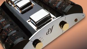
Sugden A21 Series 2 amplifier
 Designed by James Sugden in collaboration with Richard Allan, is the second iteration of this milestone Class A transistorised amp the one to buy? It's time to check it out...
The late '60s provide an interesting choice of equipment for the vintage hi-fi enthusiast. The rapid development of high-quality transistor amplifiers during the period resulted in some intriguing models and the Sugden A21 is a fine example. Why? Because it was the first successful domestic hi-fi amp on the UK market to offer a fully transistorised implementation of Class A.
To understand why this was a significant step forward it is useful to briefly remind ourselves what a Class A amplifier is. One key point to bear in mind is that amplifier classes are not intended to be hierarchical, despite their frequent misuse in advertising. The three basic classes – A, B and C (the latter not used in audio) – merely serve as engineering shorthand to describe the conduction angle of the valves or transistors in the amplifier's output stage and as such are not meant to denote an index of overall merit.
Push 'N' Pull
This concept is easiest to appreciate in amplifiers having push-pull output stages. As the name suggests, the push-pull layout has one valve or transistor to push the loudspeaker cone towards the listener and one to pull it back into the metal basket behind it. This is a practical and effective way of constructing an amp, hence its almost universal popularity. In a Class A implementation of this principle both valves or transistors are held in conduction all the time, meaning that even when the loudspeaker cone is pushed fully outwards, the 'pull' part of the stage is still conducting slightly. Contrast this with Class B, where the half of the stage that is not in use at any given time is cut off completely. This saves power but results in bursts of distortion at the inevitable point of discontinuity where control passes from one half of the stage to the other.
Known as 'crossover distortion', this is why Class B amplifiers are only usually found in portable units where battery economy is more important than sound quality. Class A amplifiers are free of this effect, resulting in low distortion figures without the need for large amounts of negative feedback. The disadvantage of Class A is that it is inefficient. This is because no more than 50% of current that passes through the output stage contributes to the signal driving the loudspeaker, the remainder wasted as heat.
Tough Sell
Inefficient amplifiers require large power supplies, highly-rated output devices and elaborate cooling schemes – all expensive items that raise the cost of the finished product. In addition, since so much power is lost as heat, less remains to drive the loudspeakers. These factors combine to give the typical Class A amp a poor price-to-power ratio, making them a tough sell.
To avoid these problems, the bulk of the industry decided on a compromise where the working regions of the two output transistors were made to overlap slightly so that at any given time at least one of them was delivering reasonable power. Known as Class AB, this mode of operation rapidly became the norm. As a comparatively inexpensive Class A design, the Sugden A21 can therefore be considered unusual.
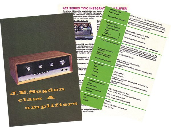
The original A21 amplifier first appeared in 1968 and was marketed by Richard Allan [HFN Apr '11]. As the design gained traction, Sugden took over the distribution of the unit itself, adding its name to the front panel and fitting a headphone socket. The first amps were hand-built and relied on individually selected components to achieve the specified performance and good reliability.
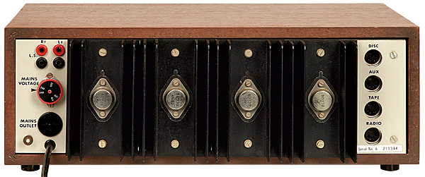
As demand took off this was no longer a viable way to proceed, so in 1969 the Series 2 model was introduced. The big change at this point was the use of new output transistors, with BDY38s replacing the original BD121s. At the same time, the circuit was modified to do away with the 'select on test' components and the supply voltage was raised slightly, increasing the output to 12W per channel. To produce even this amount, around 60W was lost as heat, even under zero output conditions. A substantial power supply was therefore required. This comprised a high quality mains transformer with dual secondary windings, each feeding a separate rectifier arrangement for each channel. The comparatively small amount of power needed by the preamplifier was tapped off just one of these – not that this made any real difference to the overall balance of things. The power amplifier modules were separate too, making the Series 2 A21 effectively a dual mono design.
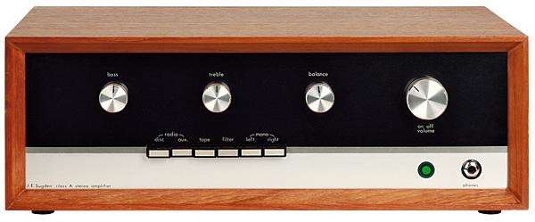
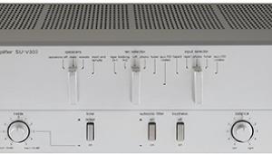
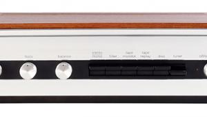
The units were constructed around a sturdy chassis made from simple steel pressings bolted together. These were assembled at certain strategic points with insulating shims and plastic screws to prevent internal earth loops forming – a neat touch. The preamp was located in a screened compartment at the front and was a sophisticated design incorporating an MM phono stage and a tape loop. Front push buttons were used for source selection and to cut in the scratch filter, as well as selecting the option to play either stereo channel through both loudspeakers or to work in mono.
Lacking a purpose-built switch bank, Sugden instead used individual latching buttons but arranged the logic of how they worked so that any combination gave a coherent result. For example, pressing either the disc or the auxiliary button selected the relevant function, but pressing both together selected the tuner input. Releasing both muted the amplifier, should one wish to do this.
A Dozen Watts
Sugden's advertising extolled the virtues of Class A operation, but rather misleadingly contrasted this with Class B, which wasn't used by any of the company's competitors. The claimed performance figures were not groundbreaking either, with 0.1% harmonic distortion at 7.5W output. To put this into perspective, the Leak Stereo 30 transistor amplifier of 1963 could offer 0.1% at 8W, without resorting to Class A techniques.
An output per channel of 12W wasn't a big deal either, even in the late 1960s. Nevertheless, the A21 Series 2 soon won friends and became a popular amplifier. It remained on sale until 1972 when it was replaced by a new range of models including the very successful A48.
![]() Tim Listens
Tim Listens
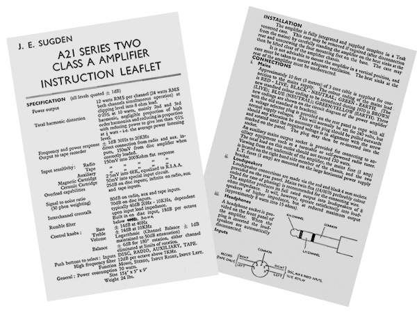
Setting up the A21 Series 2 is made easier by the use of the now commonplace 4mm sockets for the loudspeakers. Inputs are all 5-pin DINs, but these are wired in the standard fashion so suitable adapters are easy to obtain. However, the auxiliary input is a little too sensitive for a CD player with a conventional 2V output so an in-line attenuator may be necessary to avoid the volume control having a snatchy action at low listening levels.
|
| |||||||||


| Equipment Reviews | Music Reviews Awards | Latest News Features | Resources Newsletters | Subscriptions |
WHERE TECHNOLOGY BECOMES ENTERTAINMENT
 © 2026 Hi-Fi News
AVTech Media Ltd
All rights reserved