Some Like It Hot
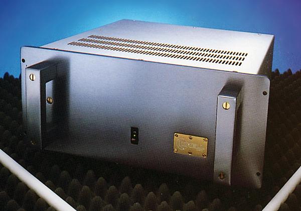
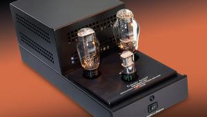
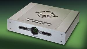
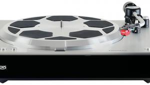
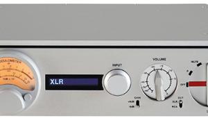
 John Atkinson heats up his listening room with a Class A amp from Krell
It used to be said that the only true way to learn was to find out something for yourself, then it will stick when all book-learning has long since been shed. This was drummed into me when I was working on the development of LEDs (green ones, to be precise).
Having grown a diode junction on a crystal slice of gallium phosphide, the simplest way to see if, indeed, it was a junction, was to put some volts across it to examine its characteristic. Unlike a resistor, current doesn't immediately flow through a diode junction when a voltage is applied. Instead, as the potential is slowly raised, for a while effectively nothing happens.
However, as the threshold voltage is reached, the diode starts to conduct and current increasingly flows until we have a normal linear relation between voltage and current. When I moved on to transistors, it came as no surprise that in exactly the same way, there existed a threshold base-emitter voltage below which a transistor will not turn on. This voltage, around 0.1V for germanium and 0.6V for silicon types, is the 'cut-in' voltage.
The Class Problem
What did come as a surprise was the fact that amp designers were quite happy to use the, then relatively new, transistors in such a manner that they were being turned on and off by the signal. This meant that they were taken through this gross nonlinearity in their transfer characteristic on every cycle.
I should take a short detour here in order to explain more fully. The output stage of a power amplifier in its simplest form consists of a valve or transistor used as a voltage follower with a gain of one: the signal is amplified by a previous stage to the appropriate high voltage and the voltage follower delivers this high voltage to the load from a suitably low source (output) impedance.
The output stage therefore acts as a current amplifier and in order to handle the signal without distortion, the device must be operated in a linear portion of its characteristic, ie, well above the cut-in voltage. The device therefore has to carry a standing bias current in order to place it in this linear region and conduct all of the time. This is termed Class A operation.
In practical power amplifiers, this output stage consists of two voltage follower transistors with the load connected to the point between them. This is often termed push-pull operation as one device literally 'pulls' the load while the other 'pushes'. However, rather than have both pulling and pushing all of the time, it would seem to make sense to have one device just handle the positive halves of the waveform, and the other handle the negative halves, each being turned off completely when the other is conducting. With this approach, there is no need for a standing bias current and the devices only conduct current when a signal is being amplified.
The advantage of this 'Class B' operation are obvious. A Class A circuit, because it conducts all of the time, even when there is no signal, is very inefficient, the wasted power being dissipated as heat, implying a power supply larger than would be dictated by the demands of the signal alone and requiring an effective method of dissipating the heat. Even when a signal is being handled, the theoretical maximum efficiency only approaches 50%. A Class B circuit, however, doesn't waste any power when there is no signal and can reach a maximum efficiency of 78.5% when handling a signal, meaning that the amplifier can be lighter (and cheaper).
Up The Junction
But – and this is a very large 'but' – Class B operation is turning those devices off and on continuously; and in the case of transistors, swinging each of them through that non-linear region around and below their cut-in voltage. The result is that every time the signal crosses from positive to negative, distortion is introduced. This 'crossover' distortion consists of very high order harmonics and is very audible. It is also independent of level, so as the signal decreases, distortion increases as a percentage of that signal.
And there other factors not present with Class A. The first is thermal stability. The voltage or emitter follower output stage, as already described, is effectively a current amplifier. But the current gain of a transistor is dependent (in a non-linear manner) on junction temperature: if that fluctuates, the current amplification of the transistor will be modulated by the temperature change. In Class A, the transistor is in thermal equilibrium: effectively it carries the same current whether signal is present or not.
In Class B, however, because no current flows with zero signal, to some extent the current gain, governed by the thermal time-constant of the transistor, will be modulated by the signal. In the extreme case, this is the definition of thermal runaway, where current gain and junction temperature pull each other up by their bootstraps until the transistor fails catastrophically. Below that level, it is yet another distortion to be looked after by the universal panacea of negative feedback.
As well as the current gain, the base-emitter cut-in voltage of the transistor is related to temperature. For changes in ambient temperature, this is normally compensated by keeping a diode in the bias circuit in close thermal contact with the power transistor. But for rapid Class B large-signal-related changes in junction temperature, such a diode will not be near enough to compensate in time and the result could be a shift in the operating conditions of the transistor, again with the possibility of signal related non-linearity.
With Class A operation, the relative thermal stability and the fact that the transistors are not operated near the cut-in voltage renders it immune to this kind of effect.
Constant Stress
Finally there are the effects of the power supply. Probably to over-simplify, the output transistors can be regarded as variable switches between the power supply reservoir capacitors and the load, and if this is the case, changes in power supply conditions might be thought to have a major effect on sound quality.
With Class A operation, the power supply is under constant stress whether signal is present or not. As long as the maximum signal voltage swing remains below the troughs of the ripple, the power supply is regulated (but without the isolation from the mains provided by a 'real' regulator, of course).
With Class B, the demand on the power supply is entirely signal-related. If the power supply is regulated, or at least of a low enough impedance across the audio band to minimise any such effects, then there should be no problems. But if the power supply is the first area to be compromised in the need to keep costs down, as it often appears – after all, why go to the expense of a transformer, capacitors, etc, capable of giving the current required at maximum signal voltage if only rarely will it be needed – signal-modulation of such factors as power supply impedance may well occur.
|
| |||||||||


| Equipment Reviews | Music Reviews Awards | Latest News Features | Resources Newsletters | Subscriptions |
WHERE TECHNOLOGY BECOMES ENTERTAINMENT
 © 2026 Hi-Fi News
AVTech Media Ltd
All rights reserved