Ringing on the ears...

Imagine that instead of each of your stereo loudspeakers sitting in splendid isolation, optimally aligned with respect to the listening seat, there was a large band of metal or plastic curving between them, joining the two cabinets. If you know anything of loudspeaker design and the efforts taken to quell structural resonances, you'd immediately suspect this structure of colouring the sound and – by carrying vibrations from one speaker to the another – of messing with the stereo image.
Anyone who built such a structure would be thought a fool, and yet this is little different from the standard design of over-ear headphone that we've accepted for decades, where two capsules are linked by a headband. If it would be so obviously bad for loudspeakers, why do we readily accept that it's OK for headphones?
Poor Control
Those of you who read my headphone reviews in HFN will have noticed me banging on recently about headband resonances and how poorly controlled they are in some designs. To date my comments have been purely subjective, based on wearing the headphones during the lab test of impedance versus frequency which squirts pink noise into the left capsule only.
Commonly I hear a character being imparted to the pink noise which disappears if I reach above my head and grasp the headband with my hands to provide damping – a sure sign of structural resonance that's sufficiently severe to be audible. At the same time the sound becomes more clearly localised in the left channel, rather than being spread out towards the centre and right of the soundstage as a result of vibration being carried by the headband to the other capsule.
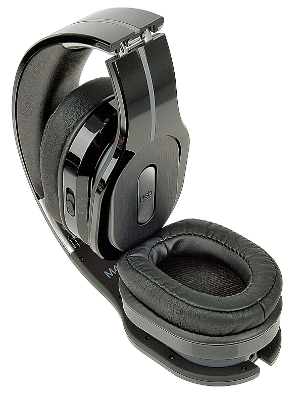
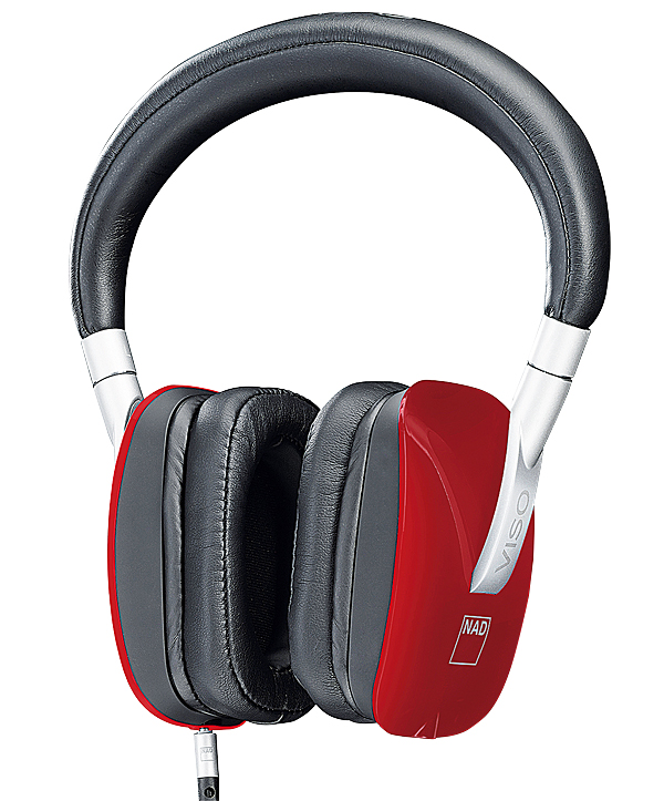
I thought it high time to attempt a measurement of this effect, not only to quantify it but to see how easily headphone manufacturers might themselves contrive to measure it and so take the necessary steps to suppress it. I suspect that too many of them are falling down on the job. So I assembled the artificial 'head' I use for headphone testing – actually a layered assembly of cut MDF sheet glued together to form an approximate head shape, with a GRAS 43AG ear and cheek simulator let into one side – and initially brought up two headphones from the basement that had evinced headband resonances when I reviewed them. These were the PSB M4U 2 [see HFN Dec '13] and the NAD HP50 [HFN Jan '14].
Simple Test
The test procedure I'd devised was as simple as could be: first measure the frequency response of the left capsule in the normal way then, while still sending signal to the left capsule only, turn the headphone around and measure the frequency response of the sound being carried over to the right capsule.
That both the PSB and NAD were closed-back types would clearly facilitate this procedure as the artificial ear is then doubly isolated from 'hearing' the active capsule via any acoustic radiation into the room. But if the results were interesting, of course I'd want to try to measure open-back models too.
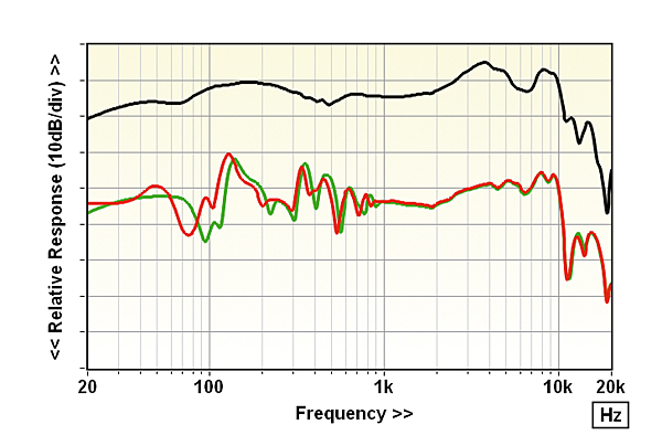
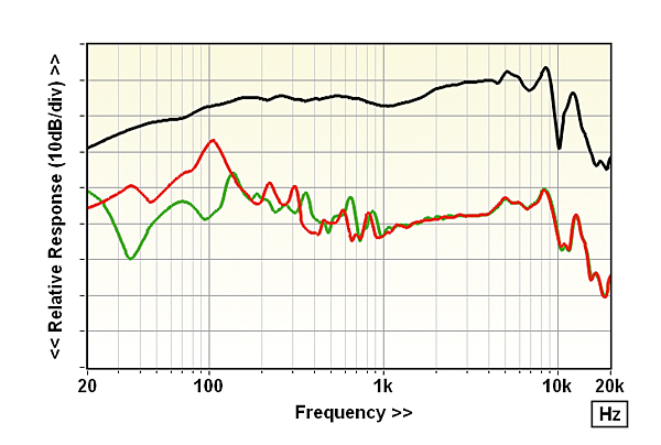
The results from the PSB and NAD are summarised in the first two sets of frequency response graphs, Figures 1 and 2, which each overlay three traces. The top, black trace is the response measured from the active (left) capsule with the headband raised from the artificial head; the red trace is that measured from the inactive (right) capsule, again with the headband raised clear of the head; and the green trace is from the inactive capsule but with the headband lowered on to the head to provide some damping. In both graphs (and all the others appearing on these pages) the vertical division is 10dB.
Telling Results
Straightforward this may be as a test procedure but, as the graphs show, it appears to elicit telling results. In both cases the responses for the inactive capsule quite closely mirror those of the active capsule above 1kHz, albeit 30-40dB down. This apparently represents the vibration carried over from the active capsule via the headband. Below 1kHz the responses from the active and inactive capsules are significantly different, the peaky nature of the inactive capsule response and the changes that result from lowering the headband onto the head indicating that the disparities are due to resonances within the structure of the headphone, principally the headband.
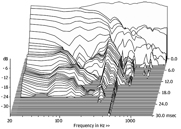
Indeed, ripples in the active capsule response at around the same frequencies as the peaks in the inactive capsule response suggest that headband resonances are having an effect on the output of the active capsule too. This is supported by the graph in Figure 3 which shows a cumulative spectral decay waterfall from the NAD's left capsule, over the frequency range 20Hz-1kHz. The resonances clearly visible at around 200 and 300Hz correspond with peaks in the inactive capsule frequency response.
Head In The Way?
At this juncture some of you may be thinking: just a minute, can we be sure that what we are looking at here is vibration carried from the active to the inactive capsule via the headband and not via the structure of the artificial head?
While there's every reason to suppose that the earpads of the active capsule will provide compliant isolation of the driver reaction force, nevertheless this is an important thing to check. And it's easily done. I used a small baffle to close off the active capsule and then compliantly isolated it (and thus the active capsule) from the head using a coil spring of high enough compliance to ensure effective vibration isolation from a low frequency.
|
| |||||||||


| Equipment Reviews | Music Reviews Awards | Latest News Features | Resources Newsletters | Subscriptions |
WHERE TECHNOLOGY BECOMES ENTERTAINMENT
 © 2026 Hi-Fi News
AVTech Media Ltd
All rights reserved