Creek CAS4040 amplifier
 The British contender for the late '70s budget amp crown won the hearts and wallets of many a budding audiophile thanks to some canny tech. How does it sound today?
In the early days of hi-fi, the budget amplifier was usually considered an object of disdain, to be quickly upgraded as soon as funds allowed. More capable designs such as the NAD 3020 changed this view and by the late '70s improvements in component technology had made it possible to produce really good amplifiers that still could be sold for reasonable prices.
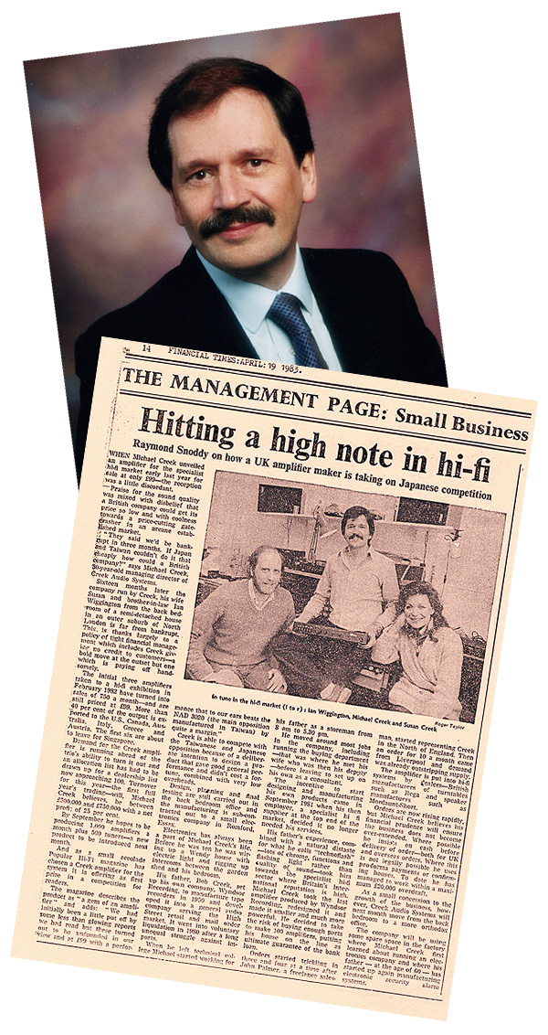
It was the success of the NAD 3020 that encouraged Mike Creek to enter the market with his own design, the CAS4040. At this time a low-volume model from a specialist British manufacturer carried a certain cachet. After all, such components were unusual at the £100 level where this amplifier was initially placed. Strong orders from dealers quickly followed and Creek Audio Systems found it had scored a hit with its very first product.
Quite A Feat
In order to be priced competitively against units whose construction benefited from far greater economies of scale, the electronic design of the CAS4040 had to be particularly frugal. When using the line level inputs (tuner, tape, etc) the signal passed through a mere seven transistors per channel – quite a feat given the 2x30W output power claimed for the unit.
To simplify the design, a single rail supply was used in conjunction with AC coupling to the loudspeakers via a pair of 3300μF electrolytic capacitors. Further savings in parts were made by making the treble and bass controls part of the power amplifier's feedback loop rather than as a separate, dedicated stage. Both techniques had been seen in low cost equipment before, but it was in the choice of output stage topology that the Creek CAS4040 really stood apart.
By the early 1980s, the design of small hi-fi amplifiers was largely a settled matter, with Class AB type circuits dominating, either formed from discrete components or packaged into large integrated circuits called 'hybrid chips'. The Creek design represented a radical departure from these ideas by employing a Class B circuit.
Amplifier classes have been discussed in these pages before, most recently in the reviews of the Sugden A21 [HFN Dec '17] and the JVC A-X4 [HFN Oct '17]. Readers may recall that in Class A and Class AB amplifiers, the conduction periods of the two output transistors overlap so there is no discontinuity in the drive to the loudspeaker. In a true Class B design this is not the case. Rather, power is saved and dissipation reduced by switching one transistor fully off before the other begins to turn on. Although efficient, this method traditionally produces too much distortion for high-fidelity use, hence the rarity of Class B designs in our field.
Problem Solved
Creek used the established method of applying copious negative feedback around the amplifier's output stage to solve the problem. This effectively makes the output transistors jump the gap over which neither is working, reducing the time over which the loudspeaker is no longer being controlled. Nevertheless, some early reviews of the original version noted that distortion levels were high when compared to those of conventional designs, despite there being some overall promise shown. The answer was to include a few extra components around the output transistors, which brought them closer towards the cusp of conduction at all times. This revision tamed the worst of the CAS4040's habits and is present in the bulk of the units encountered today [and confirmed in PM's Lab Report].
More Improvements
In fact the amp underwent quite a few changes over its six-year production life. For example, the PSU for the low-level stages was improved with the addition of an electronic filter circuit. Also, different output transistors were tried when the original types became difficult to source – even though their lower gain required additional drivers to be included. And for the last batches of units made, the phono stage, which was originally implemented in a single integrated circuit, was replaced with a comprehensive arrangement using ten separate transistors.
The first units had a high-pass filter switch that implemented an IEC-type low bass roll-off for the phono input, but this was later repurposed as a flat –20dB mute function. The aux input too, was additionally labelled as suitable for CD – a popular marketing move at the time. Production continued until 1988, when the Series 2 model was introduced. Despite the shared name, the new amp was a far more conventional design than its predecessor.
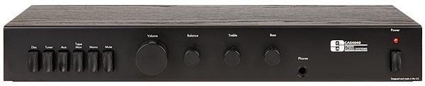
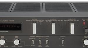
Mike Creek explained that since students were part of his target market it was important that the CAS4040 was made as compact as possible. Here the design can be said to be a complete success and when first encountered the unit's diminutive size is still surprising – it looks like an A&R A60 [HFN Jul '15] made to two-thirds scale. Despite this, the controls are well laid out and easy to use, although the source selector keys do bear a striking resemblance to those found on the Amstrad IC2000 Mk III...
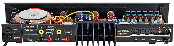
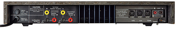
As for the amplifier's fit and finish, it has to be said that these lag behind the international standards of the day, with a simple vinyl-wrapped chipboard bonnet and a matt black fascia with basic screen-printed white legends forming the visible parts of the cabinet. To the rear, the loudspeaker connections are recessed 4mm sockets so bare wires cannot be accommodated and cables with suitable plugs need to be sourced.
Smooth Operator
There are two options when connecting the loudspeakers: either directly or via the switch contacts in the headphone socket. The manual states that the former yields better sound quality, although in practice the difference is marginal at the power levels that this unit can produce.
Inputs are predominantly via 5-pin DIN sockets mounted directly on the PCB and not supported by any of the casework, which is a familiar method of construction for this type of equipment (the A&R A60 is the same, for example). Being a later model, the turntable inputs of our sample are RCA sockets, still PCB mounted and painted to denote the left and right channels. A small heatsink completes the rear aspect of the unit, minimal cooling requirements being a key Class B virtue.
There are no protection circuits or muting relays in this design with the result that switch-on is accompanied by a big thump through the loudspeakers. Noise and hum (both electrical and mechanical) are well suppressed and the various knobs and switches work smoothly and predictably, although the treble and bass controls have a limited range and the volume control has spurious mechanical click-stops to make you think its a switched attenuator (which it isn't).
|
| |||||||||


| Equipment Reviews | Music Reviews Awards | Latest News Features | Resources Newsletters | Subscriptions |
WHERE TECHNOLOGY BECOMES ENTERTAINMENT
 © 2026 Hi-Fi News
AVTech Media Ltd
All rights reserved