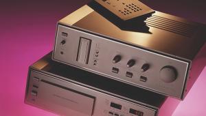
Carver M-400 A Cube
 Tiny amp, lashings of power... Martin Colloms lifts the lid on a box of tricks
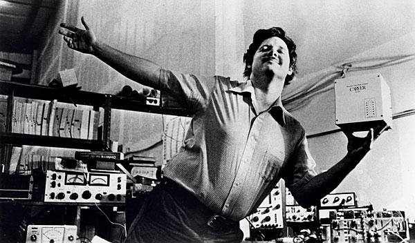
The long awaited Carver Cube power amplifier is at last available in the UK. Bob Carver, its designer, is not a particularly well known figure in the UK but most people have heard of Phase Linear, which was founded by him, and he also designed its range of products. His special interest has been in high-power amplifiers, with the 400 B and 700 B Phase Linear models now audio legends.
Carver does tend to use pseudo-technical jargon when naming the operating functions in his products, which, to jaundiced British ears at least, smacks of commercial showmanship. However, it is clear from his frequent indulgence in pure research, for example into the audibility of crossover distortion, that his technical base is strong, and not flamboyant window dressing.

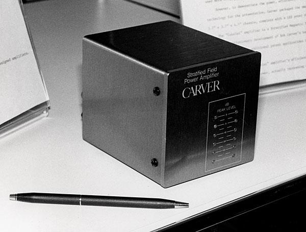
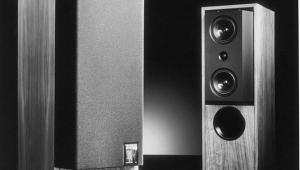
In its latest form the Carver M-400 A, or 'Cube' as it has come to be known, has been further refined, particularly with regard to its compatibility with UK mains supply. Taking its most remarkable aspects first, it aims to provide a total of 500W from a 17cm cube, which may be held in one hand as it weighs just 4.4kg (9.8lbs). All this at a price of around £400. There we have it in a nutshell – one of the industry's most powerful amps costing less than £1 per watt, and in terms of both dimensions and mass, about one quarter of conventional rivals!
Mystery Play
By designing the M-400 A so that one channel is inverted (negative pulse output for a positive pulse input) and the other non-inverting, the simple expedient of mono feed to both channel inputs allows the output to be taken in bridged mode from the two 'positive' speaker terminals. On peaks into 8ohm speakers I found the M-400 A to be capable of 1200W comparing with the continuous bridge specification rating of some 500W. In programme terms we arrive at a figure of a mere 33p per watt in bridge mode!
When first announced much emphasis was laid on its mysterious operating principles, and even those skilled in the art were foxed by expressions such as 'Magnetic Field Power Amplifier' – a label that still persists on the faceplate of the M-400 A. However, on the basis of a more conventional interpretation of amplifier principles the circuit can be stripped of its mystique and yet still make for interesting reading.
Some of the more convoluted explanations to have seen print include a representation as a magnetic amplifier arranged as a 'push pull amplitude modulation detector' with negative feedback to increase detector bandwidth and reduce distortion. This is a most cunning reversal of the more conventional representation as, say, a feedback amplifier with auxiliary higher voltage power rails used according to power levels. The supplies are fed from a switched-mode power supply whose regulation is controlled by the predicted load demand.
The M-400 A is claimed to be highly efficient, and the very low heat output even under healthy music drive does confirm this. This efficiency has been achieved by employing a very low idling sliding bias current for the output stage, this representing the main static heat source. If we were to assume that a ±80V power supply is required to produce the 250W typical output and that the usual idling current is 50mA (the so called A/B bias), then the static dissipation for two channels is 16W, which would warm noticeably a small box like the Cube.
On The Rails
The latter, however, barely increases in temperature above the ambient, and Carver's solution to this apparent paradox relates to the multiple power supplies. When idling, only the lowest supply rail pair are active (the ±25V), and in addition, a low bias current is used, which has the effect of bringing the dissipation down to 2W or so per channel (this figure does exclude power dissipation in other sections of the circuit). The amplifier's efficiency is maintained at higher power levels since it only draws the available supply voltage in proportion to the signal demand. If the full 250W equivalent power rails were to be permanently engaged, as occurs in a single supply rail pair conventional amplifier, then the dissipation as waste heat in the amplifier would be nearer 100W.
I feel the expression 'magnetic amplifier' is a misnomer, since the 'magnetic' part of the design does not amplify in the normal sense. Given larger heatsinks, and a beefy 2x80V power supply, the essential amplifier part of the M-400 A can be made to run conventionally and discussed in straightforward terms.
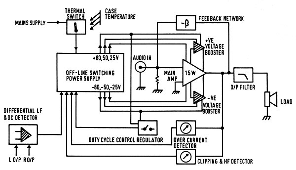
To understand the Cube it is essential to break down the system [see Fig 1] into its fundamental components. If we temporarily ignore the entire area of the power supply including the multiple rails, we find a fully symmetrical push/pull audio amplifier [see Fig 2].
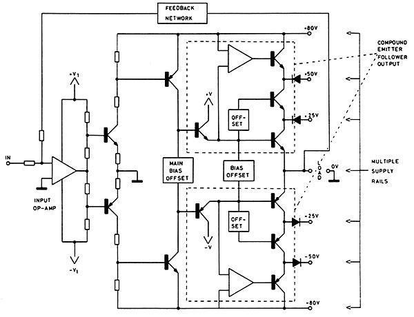
The input is DC-coupled to the differential input of an IC op-amp and a second differential pair of discrete transistors takes the signal fairly conventionally to a pair of balanced common emitter stages. These are linked via the main bias network. In simplified form the output stage is essentially a complementary emitter follower.
The innermost pair operate from ±25V rails and constitute a 20W Class A/B linear output stage, and stacked on either side of this pair is another pair of output transistors, commutated or switched by catching diodes and some driver circuitry. These are linked to ±50V supply rails and accommodate the swing of signal peaks between ±25 and ±50V. A third pair, the outermost, are fed from ±80V lines, these using additional driver and bias circuitry for clean operation.
For power levels below 20W, the additional transistors and rails are never invoked, and no difference in operation from a conventional amplifier should be apparent. Only over the upper 10dB or so of the peak full power dynamics will the amplifier almost instantaneously cross over or, more accurately, switch-in the extra transistors and associated supplies required to pass the peak voltage demand without the signal clipping.
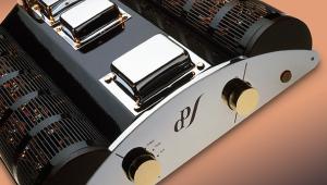
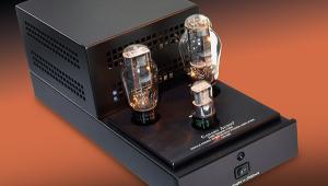
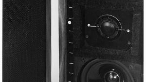
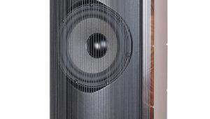
When running at full power the 80V supplies feed current to the load via the total stack of series-connected power transistors per half cycle. These – MJ 15015 and its companion MJ 15016 (now NEC equivalents) – have a massive current capacity and form the impressive array of 12 devices visible through the rear grilles, but due to the series connection an increase in the peak power output impedance of the amplifier is inevitable. Other features include the use of an LED array to show power 'on' and give an indication of power delivery, scaled '0', '–5', '–10', '–20' and '–40dB'.
Pulses 'N' Spikes
The switching speed and input current control to the booster sections of the output stage is fast, and the resultant spikes are fairly narrow and small. Their harmonics are well above the audio range and do not harmonically relate to the audio signal. To reduce radiation of the radio frequency content of the pulses, a fairly large output inductor is installed which dominates the output impedance down to frequencies as low as 15kHz.
Below 20W levels, output switching spikes do not occur but there is another minor source of noise, namely the switching part of the main power supply, and this appears on low level distortion measurements at around –75dB (ref. 0dBW), visible by spectrum analysis in the 23-70kHz range. This signal was also found to radiate from the mains supply wiring attached to the amp, particularly in the medium wave band, producing effects on transistor radios akin to a thyristor lamp dimmer at half setting, though with less severity.
Power Supplies
Returning to the amplifier system itself and in particular the power supply, the three power rail pairs (four if the low voltage op-amp supply is considered) are normal in that conventional reservoir electrolytics are employed, these being fed from bridge rectifiers. These are ±4000μF for the 80V and ±4400μF for 25V, with an effective ±1500μF for the 50V rails. It has been previously implied by some commentators that the main supply responds to the audio signal itself, but this is incorrect, because the time constants of reservoirs such as these are infinitely long by comparison with the programme.
|
| |||||||||


| Equipment Reviews | Music Reviews Awards | Latest News Features | Resources Newsletters | Subscriptions |
WHERE TECHNOLOGY BECOMES ENTERTAINMENT
 © 2026 Hi-Fi News
AVTech Media Ltd
All rights reserved